

A Device That Makes Work Easier By Changing The Size Or Direction Of A Force Is Called What?
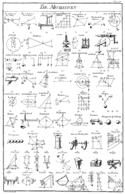
Table of simple mechanisms, from Chambers' Cyclopædia, 1728.[1] Simple machines provide a vocabulary for understanding more circuitous machines.
A simple machine is a mechanical device that changes the direction or magnitude of a force.[2] In full general, they tin can exist defined as the simplest mechanisms that employ mechanical advantage (also called leverage) to multiply force.[iii] Normally the term refers to the vi classical unproblematic machines that were defined by Renaissance scientists:[iv] [5] [6]
- Lever
- Wheel and axle
- Caster
- Inclined plane
- Wedge
- Screw
A simple machine uses a unmarried applied force to exercise work against a unmarried load force. Ignoring friction losses, the work done on the load is equal to the piece of work washed past the practical force. The automobile can increase the corporeality of the output force, at the toll of a proportional decrease in the altitude moved by the load. The ratio of the output to the applied force is called the mechanical advantage.
Simple machines can be regarded every bit the unproblematic "edifice blocks" of which all more complicated machines (sometimes called "compound machines"[7] [8]) are composed.[three] [nine] For example, wheels, levers, and pulleys are all used in the mechanism of a wheel.[10] [11] The mechanical advantage of a compound machine is just the product of the mechanical advantages of the simple machines of which it is composed.
Although they continue to be of great importance in mechanics and applied science, modern mechanics has moved beyond the view of the simple machines as the ultimate building blocks of which all machines are equanimous, which arose in the Renaissance as a neoclassical amplification of aboriginal Greek texts. The great variety and composure of modernistic machine linkages, which arose during the Industrial Revolution, is inadequately described by these 6 simple categories. Various mail service-Renaissance authors accept compiled expanded lists of "simple machines", ofttimes using terms like basic machines,[ten] compound machines,[7] or machine elements to distinguish them from the classical simple machines above. By the late 1800s, Franz Reuleaux[12] had identified hundreds of motorcar elements, calling them unproblematic machines.[13] Modern machine theory analyzes machines as kinematic chains composed of uncomplicated linkages called kinematic pairs.
History
The thought of a simple machine originated with the Greek philosopher Archimedes effectually the 3rd century BC, who studied the Archimedean uncomplicated machines: lever, pulley, and spiral.[3] [14] He discovered the principle of mechanical advantage in the lever.[15] Archimedes' famous remark with regard to the lever: "Give me a place to stand on, and I will move the Earth," (Greek: δῶς μοι πᾶ στῶ καὶ τὰν γᾶν κινάσω)[sixteen] expresses his realization that at that place was no limit to the amount of force amplification that could be accomplished by using mechanical advantage. Afterwards Greek philosophers divers the classic five elementary machines (excluding the inclined aeroplane) and were able to calculate their (ideal) mechanical advantage.[8] For case, Heron of Alexandria (c. x–75 Advert) in his work Mechanics lists 5 mechanisms that can "set a load in motion"; lever, windlass, pulley, wedge, and screw,[xiv] and describes their fabrication and uses.[17] Withal the Greeks' agreement was express to the statics of simple machines (the balance of forces), and did not include dynamics, the tradeoff between force and distance, or the concept of work.
During the Renaissance the dynamics of the mechanical powers, equally the unproblematic machines were called, began to be studied from the standpoint of how far they could elevator a load, in improver to the strength they could utilise, leading somewhen to the new concept of mechanical work. In 1586 Flemish engineer Simon Stevin derived the mechanical advantage of the inclined plane, and it was included with the other elementary machines. The consummate dynamic theory of simple machines was worked out by Italian scientist Galileo Galilei in 1600 in Le Meccaniche (On Mechanics), in which he showed the underlying mathematical similarity of the machines as forcefulness amplifiers.[xviii] [19] He was the first to explain that simple machines do not create energy, only transform it.[18]
The classic rules of sliding friction in machines were discovered by Leonardo da Vinci (1452–1519), but were unpublished and but documented in his notebooks, and were based on pre-Newtonian science such as believing friction was an ethereal fluid. They were rediscovered by Guillaume Amontons (1699) and were further developed past Charles-Augustin de Coulomb (1785).[twenty]
Ideal simple machine
If a unproblematic machine does not misemploy energy through friction, wear or deformation, so free energy is conserved and it is chosen an ideal unproblematic auto. In this case, the power into the machine equals the ability out, and the mechanical advantage can be calculated from its geometric dimensions.
Although each machine works differently mechanically, the way they office is like mathematically.[21] In each machine, a strength is applied to the device at one bespeak, and it does work moving a load, at another point.[22] Although some machines only modify the direction of the force, such every bit a stationary pulley, most machines multiply the magnitude of the strength by a factor, the mechanical reward


that can be calculated from the machine's geometry and friction.
Simple machines practise not contain a source of energy,[23] and so they cannot do more work than they receive from the input force.[22] A simple machine with no friction or elasticity is called an ideal machine.[24] [25] [26] Due to conservation of energy, in an ideal simple car, the power output (charge per unit of energy output) at any fourth dimension is equal to the power input


The power output equals the velocity of the load multiplied by the load force . Similarly the power input from the applied force is equal to the velocity of the input bespeak multiplied by the applied forcefulness . Therefore,


So the mechanical advantage of an ideal machine is equal to the velocity ratio, the ratio of input velocity to output velocity


The velocity ratio is also equal to the ratio of the distances covered in any given flow of time[27] [28] [29]

Therefore the mechanical advantage of an ideal motorcar is also equal to the distance ratio, the ratio of input distance moved to output distance moved

This can be calculated from the geometry of the machine. For instance, the mechanical advantage and distance ratio of the lever is equal to the ratio of its lever arms.
The mechanical advantage tin can be greater or less than one:
In the screw, which uses rotational motion, the input force should exist replaced by the torque, and the velocity by the athwart velocity the shaft is turned.
Friction and efficiency
All real machines accept friction, which causes some of the input power to be dissipated every bit heat. If is the power lost to friction, from conservation of energy


The mechanical efficiency of a motorcar (where 


As above, the ability is equal to the product of force and velocity, and so

Therefore,

So in not-ideal machines, the mechanical advantage is always less than the velocity ratio past the product with the efficiency η. And then a auto that includes friction volition non be able to move as large a load as a corresponding ideal car using the same input force.
Compound machines
A compound machine is a auto formed from a gear up of simple machines connected in series with the output force of ane providing the input strength to the next. For example, a bench vise consists of a lever (the vise's handle) in series with a screw, and a unproblematic gear train consists of a number of gears (wheels and axles) continued in series.
The mechanical advantage of a compound car is the ratio of the output force exerted past the last machine in the series divided by the input strength applied to the first machine, that is

Because the output force of each car is the input of the next, , this mechanical advantage is as well given by


Thus, the mechanical reward of the chemical compound machine is equal to the product of the mechanical advantages of the series of unproblematic machines that form it

Similarly, the efficiency of a chemical compound machine is also the product of the efficiencies of the serial of unproblematic machines that grade it

Self-locking machines

In many simple machines, if the load force Fout on the machine is high enough in relation to the input force Fin , the machine volition move backwards, with the load force doing work on the input force.[30] So these machines can exist used in either direction, with the driving force applied to either input point. For example, if the load force on a lever is high enough, the lever volition motility backwards, moving the input arm backwards confronting the input force. These are called "reversible", "non-locking" or "overhauling" machines, and the backward motion is called "overhauling".
Withal, in some machines, if the frictional forces are high enough, no amount of load strength tin can move it backwards, even if the input force is zilch. This is chosen a "cocky-locking", "nonreversible", or "non-overhauling" machine.[30] These machines can only be set in motility by a force at the input, and when the input strength is removed will remain motionless, "locked" by friction at any position they were left.
Self-locking occurs mainly in those machines with big areas of sliding contact between moving parts: the screw, inclined plane, and wedge:
- The about common instance is a spiral. In almost screws, applying torque to the shaft can cause information technology to turn, moving the shaft linearly to practise work against a load, but no amount of axial load force against the shaft will cause it to turn backwards.
- In an inclined plane, a load can be pulled up the plane by a sideways input force, but if the plane is not too steep and there is enough friction between load and plane, when the input force is removed the load will remain motionless and will not slide downward the aeroplane, regardless of its weight.
- A wedge tin can be driven into a cake of wood past force on the finish, such as from hitting it with a sledge hammer, forcing the sides autonomously, but no amount of compression strength from the wood walls will cause it to popular back out of the cake.
A machine will be self-locking if and merely if its efficiency η is beneath 50%:[30]

Whether a machine is self-locking depends on both the friction forces (coefficient of static friction) between its parts, and the distance ratio d in/d out (platonic mechanical advantage). If both the friction and ideal mechanical advantage are loftier enough, it will self-lock.
Proof
When a auto moves in the forward management from point 1 to bespeak 2, with the input force doing piece of work on a load strength, from conservation of energy[31] [32] the input work is equal to the sum of the piece of work washed on the load forcefulness and the piece of work lost to friction


-
(Eq. 1)

If the efficiency is beneath 50%


From Eq. 1


When the motorcar moves backward from point 2 to bespeak 1 with the load strength doing work on the input force, the work lost to friction is the aforementioned

And then the output work is

Thus the auto cocky-locks, because the piece of work prodigal in friction is greater than the piece of work done past the load force moving it backwards even with no input force
Modernistic auto theory
Machines are studied as mechanical systems consisting of actuators and mechanisms that transmit forces and move, monitored by sensors and controllers. The components of actuators and mechanisms consist of links and joints that form kinematic bondage.
Kinematic chains

Simple machines are uncomplicated examples of kinematic chains that are used to model mechanical systems ranging from the steam engine to robot manipulators. The bearings that grade the fulcrum of a lever and that allow the wheel and axle and pulleys to rotate are examples of a kinematic pair called a hinged joint. Similarly, the flat surface of an inclined plane and wedge are examples of the kinematic pair called a sliding joint. The screw is usually identified equally its own kinematic pair called a helical joint.
Two levers, or cranks, are combined into a planar four-bar linkage by attaching a link that connects the output of i creepo to the input of another. Boosted links can be attached to course a six-bar linkage or in series to form a robot.[25]
Nomenclature of machines
The identification of simple machines arises from a want for a systematic method to invent new machines. Therefore, an of import concern is how unproblematic machines are combined to make more complex machines. One approach is to attach simple machines in serial to obtain compound machines.
However, a more successful strategy was identified by Franz Reuleaux, who nerveless and studied over 800 elementary machines. He realized that a lever, caster, and wheel and axle are in essence the aforementioned device: a body rotating nigh a hinge. Similarly, an inclined plane, wedge, and screw are a block sliding on a flat surface.[33]
This realization shows that it is the joints, or the connections that provide motion, that are the primary elements of a machine. Starting with iv types of joints, the revolute joint, sliding joint, cam joint and gear joint, and related connections such every bit cables and belts, it is possible to empathize a motorcar as an assembly of solid parts that connect these joints.[25]
Kinematic synthesis
The design of mechanisms to perform required movement and force transmission is known as kinematic synthesis. This is a drove of geometric techniques for the mechanical design of linkages, cam and follower mechanisms and gears and gear trains.
Encounter likewise
- Linkage (mechanical)
- Cam and follower mechanisms
- Gears and gear trains
- Mechanism (engineering science)
- Rolamite, the only simple car discovered in the 20th century
References
- ^ Chambers, Ephraim (1728), "Table of Mechanicks", Cyclopædia, A Useful Dictionary of Arts and Sciences, London, England, vol. ii, p. 528, Plate 11 .
- ^ Paul, Akshoy; Roy, Pijush; Mukherjee, Sanchayan (2005), Mechanical sciences: engineering mechanics and strength of materials, Prentice Hall of India, p. 215, ISBN978-81-203-2611-eight.
- ^ a b c Asimov, Isaac (1988), Understanding Physics, New York: Barnes & Noble, p. 88, ISBN978-0-88029-251-1.
- ^ Anderson, William Ballantyne (1914). Physics for Technical Students: Mechanics and Heat. New York: McGraw Hill. p. 112. Retrieved 2008-05-11 .
- ^ "Mechanics". Encyclopaedia Britannica. Vol. 3. John Donaldson. 1773. p. 44. Retrieved 5 April 2020.
- ^ Morris, Christopher Chiliad. (1992). Academic Press Dictionary of Science and Technology. Gulf Professional Publishing. p. 1993. ISBN9780122004001.
- ^ a b Compound machines, University of Virginia Physics Department, retrieved 2010-06-11 .
- ^ a b Usher, Abbott Payson (1988). A History of Mechanical Inventions. Usa: Courier Dover Publications. p. 98. ISBN978-0-486-25593-four.
- ^ Wallenstein, Andrew (June 2002). "Foundations of cognitive back up: Toward abstract patterns of usefulness". Proceedings of the 9th Annual Workshop on the Design, Specification, and Verification of Interactive Systems. Springer. p. 136. ISBN9783540002666 . Retrieved 2008-05-21 .
- ^ a b Prater, Edward Fifty. (1994), Basic machines (PDF), U.S. Navy Naval Teaching and Training Professional Development and Technology Heart, NAVEDTRA 14037.
- ^ Reuleaux, F. (1963) [1876], The kinematics of machinery (translated and annotated by A.B.W. Kennedy), New York: reprinted past Dover.
- ^ Cornell University, Reuleaux Drove of Mechanisms and Machines at Cornell University, Cornell University.
- ^ a b Chiu, Y.C. (2010), An introduction to the History of Project Management, Delft: Eburon Bookish Publishers, p. 42, ISBN978-90-5972-437-ii
- ^ Ostdiek, Vern; Bord, Donald (2005). Enquiry into Physics. Thompson Brooks/Cole. p. 123. ISBN978-0-534-49168-0 . Retrieved 2008-05-22 .
- ^ Quoted by Pappus of Alexandria in Synagoge, Volume 8
- ^ Strizhak, Viktor; Igor Penkov; Toivo Pappel (2004). "Development of pattern, utilize, and strength calculations of screw threads and threaded joints". HMM2004 International Symposium on History of Machines and Mechanisms. Kluwer Academic publishers. p. 245. ISBN1-4020-2203-iv . Retrieved 2008-05-21 .
- ^ a b Krebs, Robert Due east. (2004). Groundbreaking Experiments, Inventions, and Discoveries of the Middle Ages. Greenwood Publishing Group. p. 163. ISBN978-0-313-32433-viii . Retrieved 2008-05-21 .
- ^ Stephen, Donald; Lowell Cardwell (2001). Wheels, clocks, and rockets: a history of engineering. United states of america: W.Due west. Norton & Company. pp. 85–87. ISBN978-0-393-32175-3.
- ^ Armstrong-Hélouvry, Brian (1991). Control of machines with friction. Springer. p. 10. ISBN978-0-7923-9133-3.
- ^ This fundamental insight was the subject of Galileo Galilei'due south 1600 work Le Meccaniche (On Mechanics)
- ^ a b Bhatnagar, V.P. (1996). A Complete Course in Document Physics. India: Pitambar Publishing. pp. 28–30. ISBN978-81-209-0868-0.
- ^ Simmons, Ron; Cindy Barden (2008). Discover! Work & Machines. US: Milliken Publishing. p. 29. ISBN978-1-4291-0947-5.
- ^ Gujral, I.S. (2005). Technology Mechanics. Firewall Media. pp. 378–80. ISBN978-81-7008-636-9.
- ^ a b c Uicker, Jr., John J.; Pennock, Gordon R.; Shigley, Joseph East. (2003), Theory of Machines and Mechanisms (tertiary ed.), New York: Oxford University Press, ISBN978-0-19-515598-3
- ^ Paul, Burton (1979), Kinematics and Dynamics of Planar Mechanism, Prentice Hall, ISBN978-0-13-516062-6
- ^ Rao, South.; Durgaiah, R. (2005). Engineering Mechanics. Universities Printing. p. 80. ISBN978-81-7371-543-3.
- ^ Goyal, M.C.; Raghuvanshee, G.S. (2011). Engineering science Mechanics. PHI Learning. p. 212. ISBN978-81-203-4327-6.
- ^ Avison, John (2014). The World of Physics. Nelson Thornes. p. 110. ISBN978-0-17-438733-vi.
- ^ a b c Gujral, I.S. (2005). Engineering Mechanics. Firewall Media. p. 382. ISBN978-81-7008-636-9.
- ^ Rao, Southward.; R. Durgaiah (2005). Engineering Mechanics. Universities Press. p. 82. ISBN978-81-7371-543-three.
- ^ Goyal, Yard.C.; M.S. Raghuvanshi (2009). Engineering Mechanics. New Delhi: PHI Learning Private Ltd. p. 202. ISBN978-81-203-3789-3.
- ^ Hartenberg, R.S. & J. Denavit (1964) Kinematic synthesis of linkages, New York: McGraw-Loma, online link from Cornell Academy.

A Device That Makes Work Easier By Changing The Size Or Direction Of A Force Is Called What?,
Source: https://en.wikipedia.org/wiki/Simple_machine
Posted by: washingtonpernedge1971.blogspot.com
0 Response to "A Device That Makes Work Easier By Changing The Size Or Direction Of A Force Is Called What?"
Post a Comment